Akshara Computer Center:Engineers Katta
Virtual Electronics Lab
Experiment-3 Diode Characteristics
Purpose of the experiment:
To understand (1) the diode characteristics and (2) use of LED.
To understand (1) the diode characteristics and (2) use of LED.
Theory:
Diode Charaterristics
Diode Datasheet
Diode Charaterristics
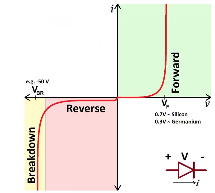
The diode conducts current in only one direction (FORM CATHODE TO ANODE) i.e. as per its symbols
arrow direction. In reverse direction current is very less and called as leakage current.
Here a chart showing characteristics of a typical diode is shown. Obviously this chart is not as per scale. It is only to understand the meaning of the terms forward voltage, breakdown voltage etc. Chart indicates that when diode starts conducting (see forward region) voltage across it practically remains constant. Typically forward voltage drop for silicon diode is 0.7 V and for germanium diode it is 0.3 V. For LED it is higher i.e. 2.0 V
Here a chart showing characteristics of a typical diode is shown. Obviously this chart is not as per scale. It is only to understand the meaning of the terms forward voltage, breakdown voltage etc. Chart indicates that when diode starts conducting (see forward region) voltage across it practically remains constant. Typically forward voltage drop for silicon diode is 0.7 V and for germanium diode it is 0.3 V. For LED it is higher i.e. 2.0 V
Diode Datasheet
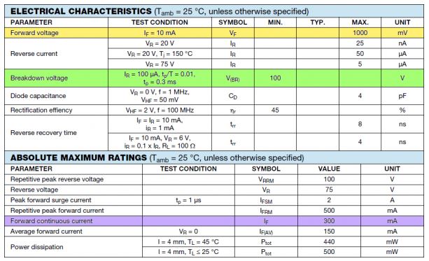
The maximum permissible value of continuous current carrying capacity of a diode depends upon
its make and specified in diode data sheet. Obviously for designing the electronic circuits you
need to understand the characteristics and should be able to read the component data sheet.
Here is the data sheet for 1N4148. In this data sheet three important parameter viz. forward voltage drop, reverse breakdown voltage and forward continuous current is highlighted.
Here is the data sheet for 1N4148. In this data sheet three important parameter viz. forward voltage drop, reverse breakdown voltage and forward continuous current is highlighted.
Explaination:
Circuit arrangement
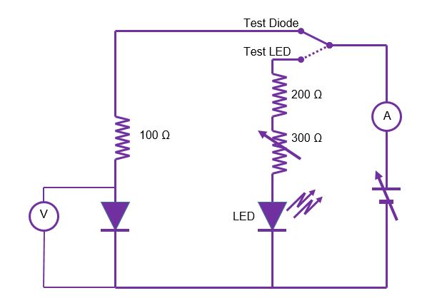
To plot the diode characteristics a circuit as shown in this figure is simulated.
It has two slide switch position. 1) To test and understood the diode characteristics and
2) to design a LED circuit as our lab activity. The circuit is energized by variable voltage
source. We will first plot the diode characteristics by measuring current through diode
(i.e. same as total supplied current) and voltage drop across the diode.
Plotting the diode characteristics
First we will discuss Diode characteristics. Let the switch position accordingly.
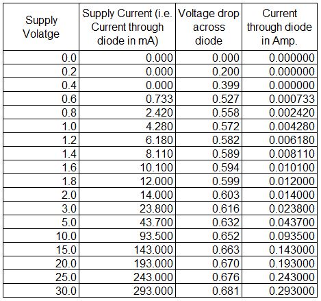
A circuit of 100 ohm resistance in series with diode is supplied through variable voltage source.
The voltage across diode and current through it is tabulated as here.
Diode Charaterristics As Per Experiment
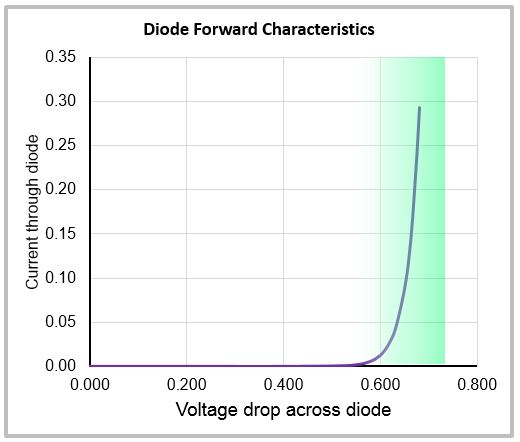
Chart of diode current verses voltage drop across it is plotted and as shown in this figure.
From the chart we can easily see that when diode starts conducting voltage across
it practically remains constant called as forward voltage drop.
In this case of simulation it is approximately 0.7 volts.
Designing the LED circuit.
Using this knowledge we will try to design a LED circuit. As per LED data sheet safe current through it is 20 mA and its forward voltage drop is 2.0 V
Hence for Vs = 8.0 V voltage drop across resistance and potentiometer is 8.0 – 2.0 = 6.0 V
Hence to limit the current to 20 mA we have to use resistance + potentiometer value as 6V/2mA = 300 ohms
(NOTE: Potentiometer put only to complete lab activity in actual design there will be only resistance)
Activity:
Recommanded to watch video before going for activities....
Start the simulation ACTIVITY "AT BOTTOM OF THE PAGE and....
- 1) Confirm few observations of diode characteristics by varying supply volatge and noting current and voltage drop across diode.
-
2) Confirm LED design for adjusting supply voltage and potentiometer positions as per above design explanation. To have series resistance and POT resistance combination
of 300 ohms; you have to put the POT position to mark E. By doing so observe supply current is below 20 mA.
Note:
1) During simulation move the slider switch position down.
For LED R is 200 ohms and POT Max is 300 Ohms having 6 major divisions i.e. each of 50 ohms; POT marked A to G counter clokwise. -
3) For LED circuit try different supply voltage and decide potentiometer position as per below table;
perform the calculations and complete the observation table.
(Note: During simulation move the slider switch position down)
Observations:
| Supply Voltage | LED Forward Volatge Drop | Voltage Across R + POT | Restinace R + Pot to be kept | Pot Position | Click to check |
| 6.0 | |||||
| 9.0 | |||||
| 12.0 |
Read the simulation circuit notes by kepping Annotation ON  After that you may put it OFF
  For reading a particular note click on
After that you may put it OFF
For reading a particular note click on